
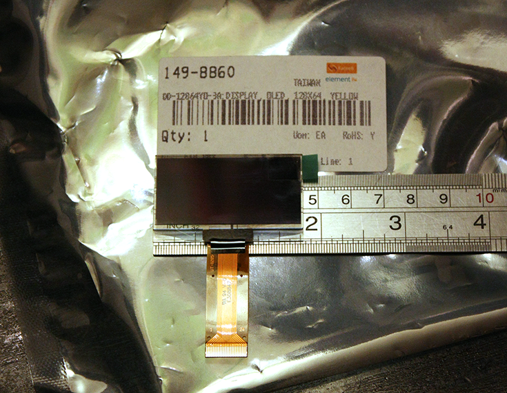
Yeah, memorable name. You might guess though, that it is 128x64 pixels, and (monochrome) yellow. I'm used to conventional LCD modules, where a 128x64 might be 100x50mm (4in x 2in) and I had read the data sheet, but I don't think I was ready for quite how small this wee beastie is:
This instantly raises an issue over the form factor. I guess it is technology intended for mobile phones, but for practical hand held test gear I think it is just a bit too small. You can get 256x64 units which are approximately twice the width, but they are twice the price too, and well into the territory of colour LCD with integrated touch panel.
I had intended to hack this straight into an Arduino or Mbed, and get a quick demo running, but a few things have stopped me. See that connector in the photo above? 24 pins, each half a millimetre apart - clearly influenced by it's mobile phone background. None of this standard 0.1" header LCD here! Even with the matching socket, it really needs a custom PCB to break out the lines. Fear not though, I have a cunning plan, which involves a load of 30AWG (0.4mm) Kynar wire.This alone is going to slow down take-up when it comes to amateur projects and even professional prototyping. Secondly, though, the module is 3.3V only. No 5V here, no sir. A few resistors should sort that problem out, but it all adds up. Having said that, I don't know of any commercial systems that run 5V any more, so it is no big issue for non-Arduino folks.
One part of the manufacturer's data informs me that I need an externally generated 12V supply, but another part tells me that it can be generated internally. We shall see.
Looking at the pinouts, it seems like it is an adaptation of the classic HD44780 chip. It isn't. It uses an SSD1305 which does waaaay more than the old chip. Unfortunately this means it takes a lot more driving too. Just booting it up takes a fairly hefty code sequence. The user can elect (by variously grounding 2 pins) to use a classic 8bit 68xx or 80xx parallel protocol or, more interestingly, use 4-wire SPI or 2-wire I2C. If the manufacturers had desired, they could have easily halved the pin-count by going serial only, and removing three "No connection" pins that they insist should be grounded. I'm sure the market for breakout boards with a boost power supply and a level converter is already out there.
So, this looks like an interesting little adventure. I can think of a few projects where a module like this would be useful, not least my JTAG adaptor. It is definitely the sort of thing I will bear in mind for future designs, possibly filling in for indicator LEDs rather than low current LCD (the OLED unit draws up to 55mA). I hope to have some shots of a demo up soon.
Thanks go out to Farnell Element-14 for supplying the Densitron DD-12864YO-3A.
No comments:
Post a Comment