
I suppose this project should really be called Antonio as it is the brother of Prospero, but it doesn’t exactly sound right for a piece of test equipment. An appropriate name evades me for the moment. It is probably just as well.
Measuring Inductance, Capacitance and Resistance.
In designing Prospero (the RF vector network analyser) it has come to my attention that the inductance and capacitance measuring equipment currently available to me isn’t exactly precision lab reference grade. A resolution of 1nF isn’t really good enough when you are working at sub-pF level. Upon investigating, it seems that a basic LCR (Inductance, Capacitance, Resistance) meter starts at around £150. If I want to measure the equivalent series resistance (and I do) then I am looking at upwards of £250. Hmm. I don’t really have that sort of money to spend on another meter, so just what is an engineer to do?
Well, after an amount of thought (somewhat less than a second), I decided that building my own was probably the best way forward. But then you knew that didn’t you!
So, what architecture? There are plenty of simple embedded micro based meter designs around, but they are all designed around similar methods and are rather limited in range and accuracy. I had specified that the unit be capable of a test frequency of at least 100kHz and most units seem to stop at 10kHz. That inherently reduces the ability to read small value components with a good degree of accuracy. I remembered that a few years ago I was sent a sample of Analog Devices’ AD5933 1MSPS 12-bit Impedance Converter. I had meant to do something with it, but it has certain limitations (which I will go into later) and at that time I was working in a lab which had nice test gear, so the chip got filed away. After a good read through of the data sheet however, I decided the AD5933 would probably take a lot of leg work out of my design and was good enough for my purposes.
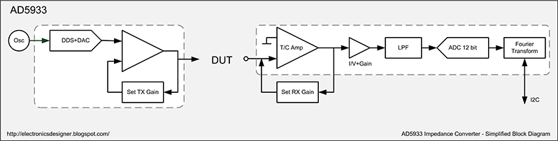 |
| Fig.1 AD5933 Impedance Converter - Simplified Block Diagram |
Never Satisfied
As I mentioned, the AD5933 isn’t perfect. The 10-bit DAC generates spurious signals outside the desired band (although the LPF filters many of these out in the receive section) it is inherently very poor at measuring low impedance values, and the maximum text frequency is limited to 100kHz. Ideally I would have liked 1, 10 or even 100MHz available to test RF components. So I set to work to design something of my own. The first result is reproduced below.
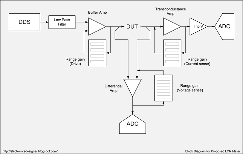 |
| Fig.2 Improved LCR Meter Design - Block Diagram |
The intention was to DDS generate a clean 24-bit sinusoidal signal in software (probably with an ARM Cortex M3) and do the D-A conversion with a fancy hi-fi chip (they really are absurdly cheap). They can be pushed to well over 200KSPS, giving a precise and clean 100kHz source with only a little filtering. Simultaneous measurement of the current and voltage components is to be done with another 24-bit 200KSPS+ hi-fi ADC chip and streamed into the processor via DMA.
To give flexibility, the output is capable of driving peak-to-peak levels between 0.01V and 10V at up to 10mA, with programmable offset. Voltage is sampled across the test ‘probes’ in a 4-terminal manner, with a set of programmable gains to ensure the best possible use of the ADC’s dynamic range. Current is measured via a transconductance amplifier (again with programmable gain) which produces a voltage proportional to the current through it, but without the ‘burden voltage’ associated with a simple resistor as used in most current measurement. This is then presented to the second ADC channel. After grabbing a large enough sample, software performs a simple Fourier conversion to the frequency domain. Comparing phase and magnitude gives us our desired parameters.
However…
In one of those moments to which most engineers are prone, I decided that wasn’t enough. I really needed 1/10/100MHz and had 14-bit 400MSPS DDS chips in stock. I could use one signal as a source, and a second (coherent) signal to compare the phase in a mixer, reading the magnitude in an ADC. Excellent.
One slight problem though. What I have actually described there is a network analyser. Basically it is a cut down version of Prospero, limiting at 100MHz instead of 500MHz, and not being able to measure the reflected signal. So what is the point making it when I will have a better tool in my hands before long? None at all! Sigh. I had gone around in a huge circle.
Back To The Beginning!
Anyway, I decided to go back to the start and go with the original AD5933 design. It can be modified to handle low impedance values, and the addition of a cheap external DDS makes the clock scale down to audio frequencies, which is handy for audio components such as loudspeakers etc. As you can see from the diagram below, the current sense gain will be selectable.
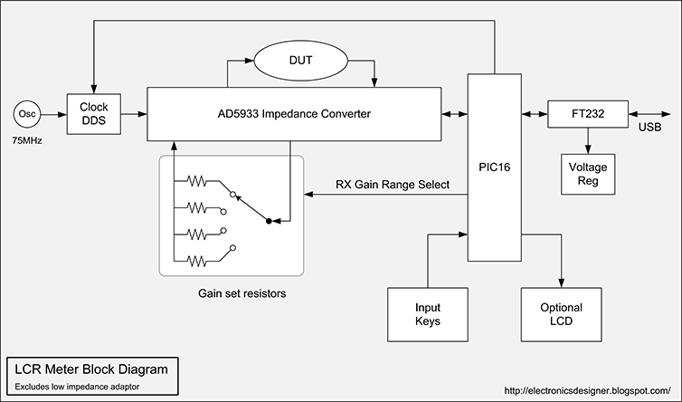 |
| Fig.3 LCR Meter Block Diagram - Excluding Low Impedance Adaptor |
Control is to be done via a simple PIC16, with connection to the PC via an FTDI USB module. In theory I could probably bit-bang the operation from the FTDI module, but that would probably end up being more expensive and more complex than a cheap and fast PIC16. With an on-board micro, I could build in an LCD and do all the maths on the embedded micro but, to be honest, it isn’t going to move outside the lab, and it is far easier to do more exotic maths on a nice fast PC with a good display. Nevertheless, I will probably provide the appropriate connections to drive a standard LCD text module.
For the moment, it is my intention to derive power from the USB connection. The entire system is low power, with the AD5933 drawing a nominal 10mA at 3V. Dropping from 5V to 3V also gives me the opportunity to provide more precise voltage regulation than USB gives, and also the ability to remove noise on the power lines, both of which improve the accuracy of the system.
In Part 2 I intend to cover the design of the low impedance adaptor, how the current range is selected, and some ideas on how the system accuracy can be improved beyond the 0.5% claimed for the AD5933. Until then, toodlepip!
Hi Mike.
ReplyDeleteDo you have an email I can contact you on? I have a few questions.
Thanks
Ryan
Hi Ryan, drop me a line on msc@digital-wizardry.co.uk
ReplyDeleteCheers!
Hi Mike
ReplyDeleteWhens part 2 coming?
Looking forward to that!
Thanks
Richard
Fingers crossed, it should be up some time this weekend. I thought I had hit a bit of a game-killer bug in the AD5933, but it looks like I will be able to work around it.
ReplyDeleteCheers!